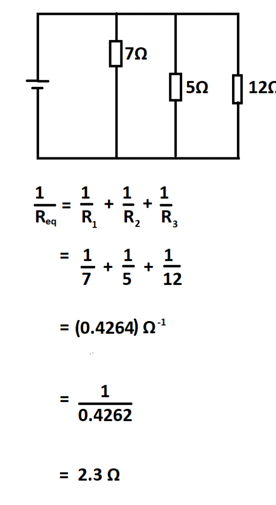


PARALLEL RESISTORS SERIES
More complex connections of resistors are sometimes just combinations of series and parallel. combination circuit: An electrical circuit containing multiple resistors that are connected in a combination of both series and parallel connections.parallel: An arrangement of electrical components such that a current flows along two or more paths.series: A number of things that follow on one after the other or are connected one after the other.If the resistance in wires is relatively large, as in a worn (or a very long) extension cord, then this loss can be significant and affect power output into appliances. Resistance in wires reduces the current and power delivered to a resistor.Various parts of a combination circuit can be identified as series or parallel, reduced to their equivalents, and then further reduced until a single resistance is left.More complex connections of resistors are sometimes just combinations of series and parallel.In a series circuit, the battery would last just as long as it would with a single light bulb, only the brightness is then divided amongst the bulbs.
PARALLEL RESISTORS FULL
Because the same full voltage is being applied to both light bulbs, the battery would also die more quickly, since it is essentially supplying full energy to both light bulbs. However, if the two light bulbs were connected in parallel, they would be equally as bright as if they were connected individually to the battery. In a series circuit, the two light bulbs would be half as dim when connected to a single battery source. This is exemplified by connecting two light bulbs in a parallel circuit with a 1.5V battery.

When resistors are connected in parallel, more current flows from the source than would flow for any of them individually, so the total resistance is lower.Įach resistor in parallel has the same full voltage of the source applied to it, but divide the total current amongst them. This relationship results in a total resistance that is less than the smallest of the individual resistances. If we substitute the values for individual voltages, we get: The sum of the voltages would equal: V=V 1+V 2+V 3, based on the conservation of energy and charge. So the voltage drop across R 1 is V 1=IR 1, across R 2 is V 2=IR 2, and across R 3 is V 3=IR 3. Using Ohm ‘s Law to Calculate Voltage Changes in Resistors in SeriesĪccording to Ohm’s law, the voltage drop, V, across a resistor when a current flows through it is calculated by using the equation V=IR, where I is current in amps (A) and R is the resistance in ohms (Ω). Resistors connected in a series circuit: Three resistors connected in series to a battery (left) and the equivalent single or series resistance (right).


 0 kommentar(er)
